As I heard that one of my colleagues at work has all the parts for MultiWii quadcopter collecting dust and cobwebs in his garage, I snatched the opportunity to practice MegapirateNG setup on Multiwii and Megapirate AIO Flight Controller w/FTDI (ATmega 2560) V2.0. This is a very interesting low-cost controller supplied by Hobbyking that uses a customised APM firmware to perform a whole range of useful functions beyond the scope of the regular RTF controller.

You can find the full description of its features on Hobbyking Website, however what certainly attracted my attention is a full range of on-board sensors required for successful multicopter performance (it can handle up to 8 rotors). Apart from that there is a useful I2C interface to communicate with external sensors (e.g. proximity sensors), OSD, telemetry and camera gimbal support. This is a pretty cool package that comes at low cost. Finally, when I have received the package of goodies and after some delays due to Christmas and other commitments, the work has begun. Of cause, my primary goal was to choose the firmware that will perform to the best of my liking (taking into account future projects). There are 2 major firmware packages that can be used on this controller. Original MultiWii firmware seems to be more a kind of a grass root project with some pretty impressive GUI developed. However, it seems to neglect some additional functionality that I would expect from a modern flight controller. Once you look at the description of MegapirateNG firmware, it becomes clear that it delivers a bulk of APM firmware capabilities. In fact these guys do a decent hack on APM firmware, which makes the adaptation to MultiWii hardware pretty smooth. Of cause, you need to use MissionPlaner to do all the setups. However, let us start from the beginning... The first thing you need to have a look at is Connecting Your Components webpage. This will give you an idea on whether what you want to do is covered by the firmware and give you a chance to make up your mind about additional parts that you might require to purchase. Another necessity: an FTDI Basic Breakout Board from Sparkfun. The USB port on MultiWii AIO controller is fragile and it makes a lot of sense to use FTDI interface, especially during calibration with MissionPlanner. If you need more explanation on how to make your FTDI cable working, please post your questions in the comment section below.

Next step (after you've assembled the hardware), flash you MultiWii with MegaPirateNG Flashtool. You can download the current version of the Flashtool from here. I have to give you a warning: do not try to use the modified version of Ardupilot-Arduino from the main website (www.megapirateng.com), as it most likely won't work. Flashtool however seems to work perfectly well.

You can see the exact setup that I used for my quadcopter at this moment of time. If you are worried about the absence of choice between "plus" and "X" versions of the frame, you shall be able to make these changes through MissionPlaner interface. Once you have the Missionplanner installed, you can use the same FTDI interface to connect to it.

The baud rate is normally pre-set to 115200, so make sure you select the right value from the drop-down window in the top right corner. Next thing you want to do is a few initial setups. Choose frame type (plus or X) from the following interface:
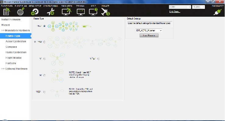
Remember, this is the only change to frame configuration that you'll be able to make at this point. E.g. changing from quadcopter to hexacopter won't work, so you should better make correct selections in the Flashtool before uploading the firmware. One of the better videos on Youtube describes the pre-sets well. Albeit in Russian. The entire procedure is quite intuitive. Nevertheless, here is a brief summary (this assumes that you have flashed the board for the first time, otherwise please follow the EEPROM erasing procedure in the video):
- Calibrate Compass
- Calibrate Accel
- Calibrate Radio (note: you might need to do radio calibration several times, as a couple of manual channel switched and reverses might be required - pay attention to throttle response and whether you are entirely happy with it. Remember, channel confusion can cause arm/disarm problems later)
- Calibrate ESCs
- Switch to failsafe page, check arm/disarm procedure. Check output channel responses. Important! - It is important to check that output channels respond correctly to your transmitter stick commands. If you had to swap receiver outputs/MultiWii inputs - it will make sense to re-calibrate the radio.
Other pre-sets that you might need to change:
- Flightmodes: these are driven by transmitter/receiver output on channel 5. Make sure you have identified the channel on your transmitter correctly. Assign appropriate flight modes to all positions of your switch. It will make sense to refer to your radio manual if you want to set more than 2 or activate channel 7 (MissionPlanner: Config/Tuning --> Standard Params)
- Modify the parameter MOD_SPIN_ARMED to "Do not spin" - this will make sure that the motors do not spin after being armed (MissionPlanner: Config/Tuning --> Standard Params)
You should be done by now and ready to go. Don't forget to affix that piece of foam (open cell) on you barometer, as even the slightest wind will drive it crazy. Ducting tape or cable ties work well unless you want to go really fancy.
